Product Description
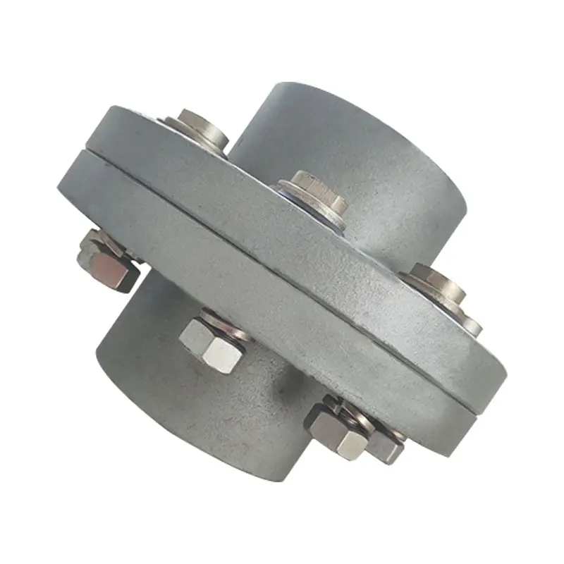
Cast Iron Steel Normex Flange Shaft Flexible Nm Coupling With Rubber
Product Description
1. Applies to flexibly drive shaft, allowing a more significant axial radial displacement and displacement.
2. It Has a simple structure and easy maintenance.
3. Disassembly is easy.
4. low noise.
5. Transmission efficiency loss, long useful working life.
Product Parameters
| SIZE | TORQUE | MAX SPEED rpm. |
BORE | BOSS DIA D |
OUTSIDE DIA OD |
LENGTH L |
TOLERANCE | POWER | SHAFT | WEIGHT kg |
||
| STHangZhouRD kg/m |
MAX kg/m |
MIN | MAX | |||||||||
| NM-50 | 1.3 | 2.3 | 13500 | 1 | 19 | 33 | 50 | 25 | 2.0±0.5 | – | – | 0.48 |
| NM-67 | 2.2 | 4 | 10000 | g | 28 | 46 | 67 | 30 | 2.5±0.5 | 1HP | 8-28 | 1.02 |
| NM-82 | 5 | g | 8000 | 10 | 32 | 53 | 82 | 40 | 3.0±1.0 | 2-3HP | 10-32 | 1.88 |
| NM- 97 | 10.5 | 19 | 7000 | 12 | 42 | 69 | 97 | 50 | 3.0±1.0 | 5-7.5HP | 12-42 | 3.54 |
| NM-112 | 16.7 | 30 | 6000 | 14 | 48 | 79 | 112 | 60 | 3.5±1.0 | 10-20HP | 14-48 | 5.4 |
| NM-128 | 26.7 | 48 | 5000 | 1B | 5 | go | 128 | 70 | 3.5±1.0 | 30HP | 18-55 | 8.1 |
| NM-148 | 41.7 | 75 | 4500 | 22 | 65 | 107 | 148 | 8o | 3.5±1.0 | 40HP | 22-65 | 13.5 |
| NM-168 | 69.5 | 125 | 4000 | 28 | 75 | 126 | 168 | 9o | 3.5±1.5 | 60HP | 28-75 | 19.3 |
Related Products
Company Profile
FAQ
Q: Can you make the coupling with customization?
A: Yes, we can customize per your request.
Q: Do you provide samples?
A: Yes. The sample is available for testing.
Q: What is your MOQ?
A: It is 10pcs for the beginning of our business.
Q: What’s your lead time?
A: Standard products need 5-30days, a bit longer for customized products.
Q: Do you provide technical support?
A: Yes. Our company has a design and development team, and we can provide technical support if you
need.
Q: How to ship to us?
A: It is available by air, sea, or by train.
Q: How to pay the money?
A: T/T and L/C are preferred, with different currencies, including USD, EUR, RMB, etc.
Q: How can I know if the product is suitable for me?
A: >1ST confirm drawing and specification >2nd test sample >3rd start mass production.
Q: Can I come to your company to visit?
A: Yes, you are welcome to visit us at any time.
Q: How shall we contact you?
A: You can send an inquiry directly, and we will respond within 24 hours /* January 22, 2571 19:08:37 */!function(){function s(e,r){var a,o={};try{e&&e.split(“,”).forEach(function(e,t){e&&(a=e.match(/(.*?):(.*)$/))&&1

Impact of Flange Coupling on Noise and Vibration in a Mechanical System
Flange couplings play a significant role in the overall noise and vibration levels of a mechanical system. The type of flange coupling used and its design characteristics can have varying effects on the system’s noise and vibration. Let’s explore how flange couplings impact noise and vibration in a mechanical system:
1. Rigid Flange Couplings:
Rigid flange couplings, being solid and inflexible connections, are generally considered to be more rigid than flexible couplings. As a result, they can transmit vibrations more directly between the connected shafts and the rest of the system. The lack of misalignment compensation can lead to higher stress on the bearings and other components, contributing to increased vibration levels.
However, rigid flange couplings are also less likely to introduce any additional sources of vibration due to their simple and solid construction. If the system is well-aligned and requires no misalignment compensation, rigid flange couplings can provide a stable and reliable connection.
2. Flexible Flange Couplings:
Flexible flange couplings are designed to dampen vibrations and shocks in the system. The flexibility of these couplings allows them to absorb and minimize the transmission of vibrations between the connected shafts and the rest of the system. As a result, flexible flange couplings can reduce overall vibration levels and provide a smoother and quieter operation.
Additionally, the misalignment compensation capability of flexible flange couplings helps to reduce stress on the bearings and other components. By accommodating misalignment, these couplings prevent the system from experiencing excessive vibrations that can lead to premature wear and failures.
Overall Impact:
The choice of flange coupling design will significantly influence the noise and vibration levels in the mechanical system. In applications where precise alignment is crucial, rigid flange couplings may be preferred despite potentially higher vibration levels. On the other hand, flexible flange couplings are ideal for systems where misalignment is expected or where vibration dampening is a priority.
It’s important to consider the specific requirements of the application when selecting a flange coupling. Factors such as torque capacity, operating conditions, alignment needs, and desired noise and vibration levels should all be taken into account. Proper installation and maintenance of the chosen flange coupling can also impact its performance in reducing noise and vibration levels in the mechanical system.
Electrical Insulation in Flange Couplings
In certain applications, flange couplings may need to provide electrical insulation between shafts to prevent the flow of electrical currents and ensure safety and proper functioning. The handling of electrical insulation in flange couplings depends on the design and materials used:
1. Material Selection: Some flange couplings are manufactured using electrically insulating materials, such as certain polymers or composite materials. These materials have high resistivity and do not conduct electricity, effectively isolating one shaft from the other.
2. Sleeve or Coating: In some cases, a non-conductive sleeve or coating is added to the coupling to provide electrical insulation. This sleeve can be made from materials like rubber or other insulating compounds.
3. Insulating Inserts: Flange couplings may incorporate insulating inserts or liners between the mating surfaces to prevent electrical conduction.
4. Dielectric Grease: Dielectric grease, a non-conductive and water-resistant grease, can be used to fill any gaps between mating surfaces and enhance the electrical insulation properties of the flange coupling.
It’s crucial to ensure that the chosen flange coupling provides adequate electrical insulation for the specific application. The level of insulation required will depend on the electrical characteristics and voltages involved in the system. Additionally, proper installation and maintenance are essential to maintain the integrity of the electrical insulation over time.

Types of Flange Coupling Designs
Flange couplings are mechanical devices used to connect two shafts and transmit torque between them. They come in various designs, each suited for specific applications. Here are the different types of flange coupling designs:
- 1. Unprotected Flange Coupling: This is the simplest type of flange coupling, consisting of two flanges with flat faces that are bolted together to connect the shafts. It is cost-effective and easy to install but offers limited protection against misalignment.
- 2. Protected Flange Coupling: In this design, the flanges are fitted with a protective cover or casing, which helps prevent dust, dirt, and other contaminants from entering the coupling. It provides better protection to the coupling components, making it suitable for outdoor or harsh environments.
- 3. Flexible Flange Coupling: This design incorporates a flexible element, such as a rubber or elastomeric insert, between the flanges. The flexible element allows for some misalignment between the shafts and helps dampen vibrations, reducing wear on connected equipment. It is commonly used in applications where there may be slight shaft misalignment.
- 4. Rigid Flange Coupling: The rigid flange coupling is a solid coupling without any flexible elements. It provides a rigid connection between the shafts, which is ideal for applications where precise alignment is critical, such as high-speed machinery or precision motion control systems.
- 5. Sleeve Flange Coupling: In this design, a hollow sleeve fits over the ends of the shafts and is bolted to the flanges. The sleeve helps provide additional support and alignment for the shafts.
- 6. Half-Flanged Coupling: Half-flanged couplings consist of two flanges on one shaft and a single flange on the other shaft. This design is suitable for applications with limited space or where one shaft is fixed, and the other requires disconnection frequently.
The choice of flange coupling design depends on factors such as the level of misalignment, speed of rotation, available space, environmental conditions, and the required level of flexibility. Proper selection of the flange coupling type ensures efficient power transmission and extends the life of connected machinery and equipment.


editor by CX 2024-05-13
by
Tags:
Leave a Reply